Relay box and Wiring for Phone and Heated Clothing

Mileage 10,187

Maintenance Summary:

I wanted a switched SAE outlet near the handlebars, into which I could plug a USB adapter to power my phone.  I needed a switched circuit so that the USB adapter wouldn’t drain the battery when the bike wasn’t running.  To that end I needed a relay and some fuses.

There’s an empty space behind the battery which seemed like a good place to install something, but it’s only 1.25″ thick.  I was going to build a custom fuse block to fit in that space when I ran across this Show Chrome fuse block.  I just happened to have a specified thickness of 1.25 inches.  I  found one for $40 on eBay, which is about what it would have cost me to build my own relay activated fuse block.   Other brand fuse blocks were both more expensive, and much thicker.

Well, the fuse-block didn’t fit in the space behind the battery, but it was thin enough to fit under the seat on top of the fuel pump.  This location has the advantage that the fuses are easy to get to.

Designed to hook up trailer lights, this fuse block had way more functionality than I needed.  All I needed was a relay to support higher current devices than would be possible to operate from the factory GPS connector.  This product provides three switched circuits.  As I wanted the ability to easily remove the fuse block from the bike I needed to install a connector.

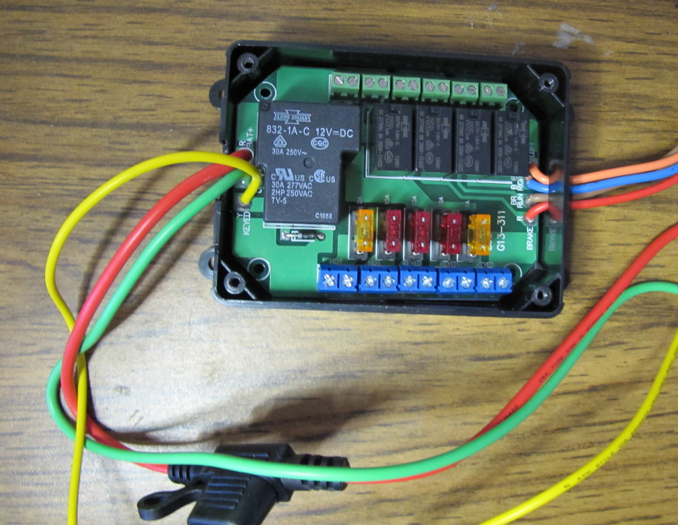
Here’s the fuse block before modification.  The wires on the right aren’t needed and the in-line fuse on the larger red wire won’t work well because it’s too far away from the battery to protect the wiring.  The large relay switches power,  the small relays for for indicator lights and won’t be used.  The unit is well made;  I like the fact that they remembered to put a diode across the relay coil to prevent voltage spikes when the coil’s magnetic field collapses.

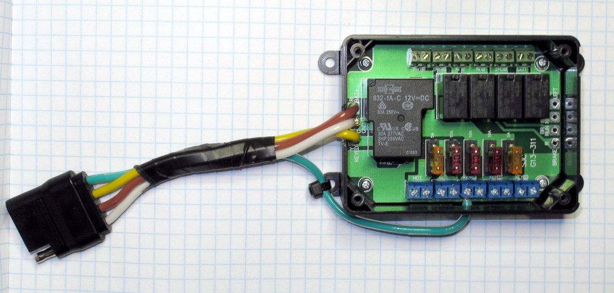
I removed all of the wires and replaced the three wires on the left with a 5′ trailer wiring harness from Harbor Freight (cost less than $7).  Here’s the modified fuse block.  The green fourth wire is the switched power that will connect to an SAE plug.  The yellow wire controls the relay.  That’s connected to wire #3 on the BMW connector.  I used white for ground and brown for power — it was the closest thing to red.

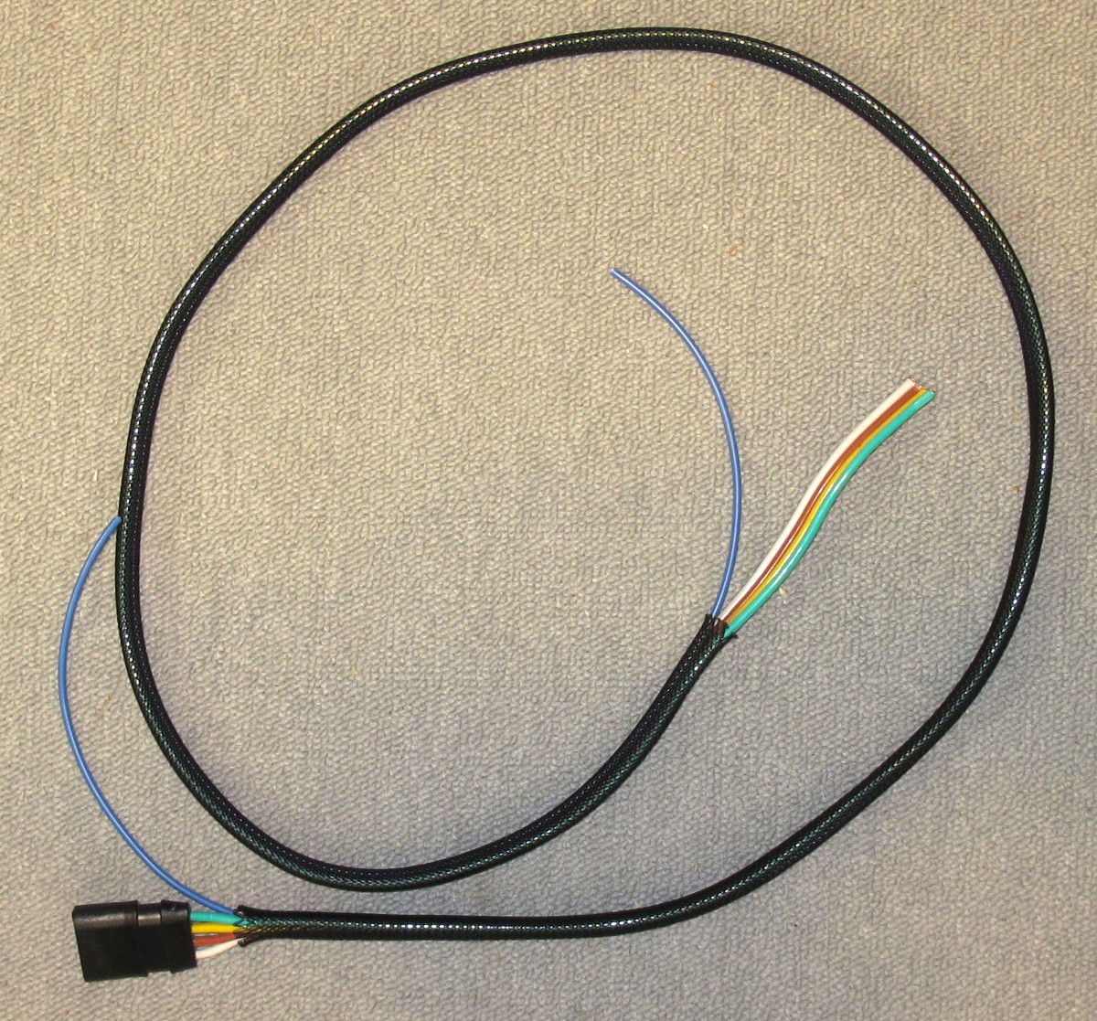
Here’s the harness ready for installation.  I’ve included an extra circuit for future use (blue wire).  The 5 foot harness ended up being about 6 inches longer than I needed.  The harness uses 14 gauge wires.

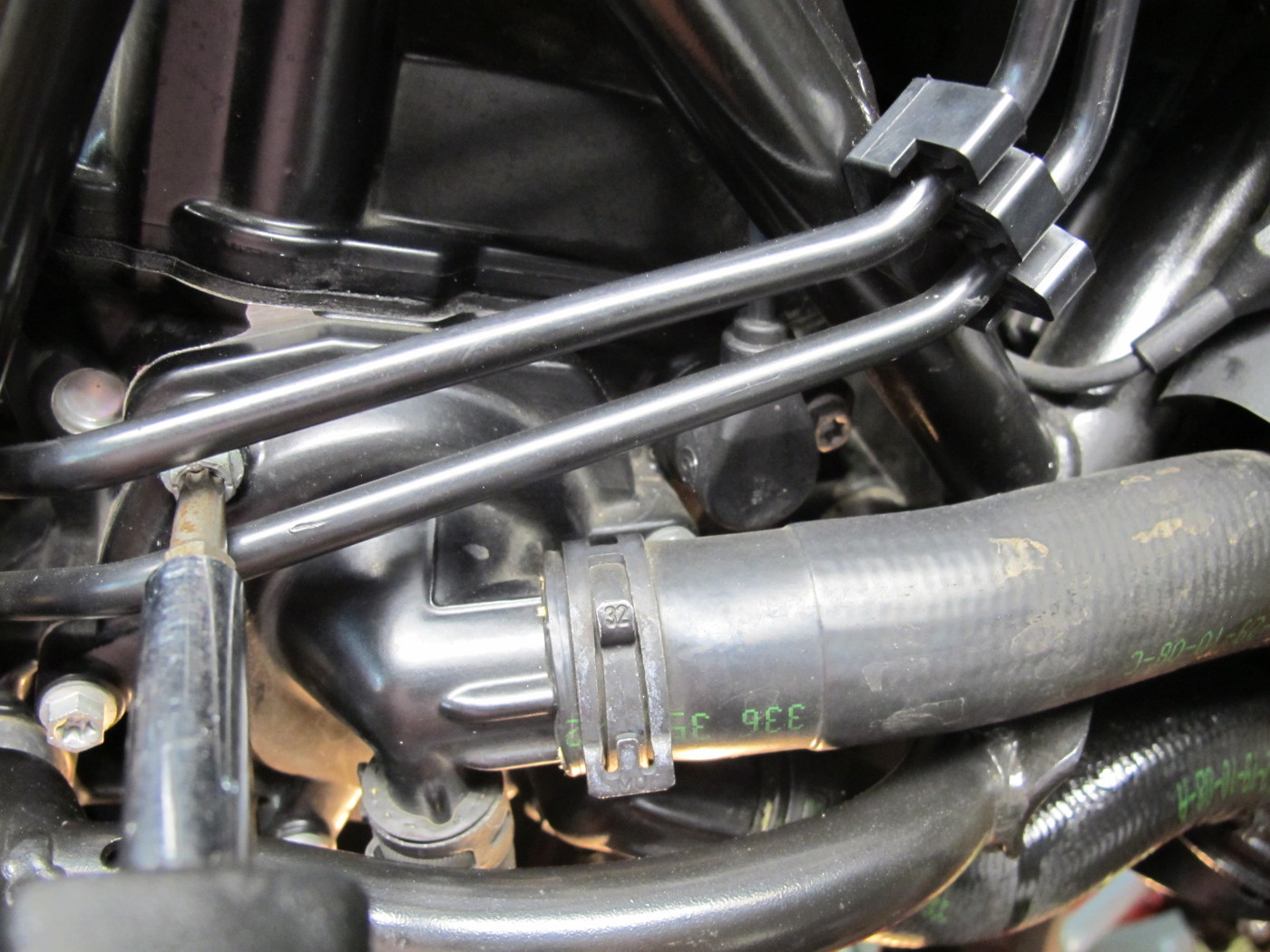
The new harness follows the same path as the factory harness.  I was surprised that the colored wires were so easy to see in the picture, probably because of the flash.  They normally look more like the picture above.

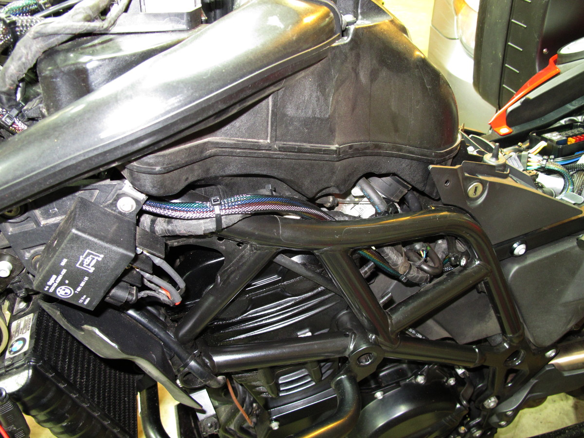
The harness terminates at the battery.  After trimming of the excess length I soldered on a ground cable and a positive cable with an in-line fuse.  Only one of the three yellow wires is used.  I just tucked the two unused wires into the cable loom.  The blue wire is the spare circuit.  The green wire connects to an SAE cable.  The ground for that cable goes directly to the battery which is why there’s one more wire on the negative terminal.  The other wires are for another, un-switched SAE circuit for use with a battery tender.

The #3 wire on the BMW plug switches on with the key and switches off about 30 seconds after the bike is switched off.  As you can see from the thin wires, this CANBUS outlet isn’t designed to source much power.  It does have enough power to operate the fuse-block relay.  The BMW repair cable set me back $22.  Ouch!  I bought this one on Amazon

The yellow wires hang over the empty space where I had hoped to install the fuse block.  It just wouldn’t fit.  Just as well, it probably would have rattled around in there anyway.

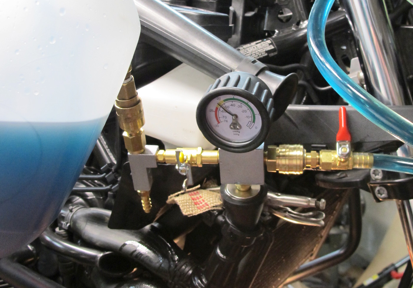
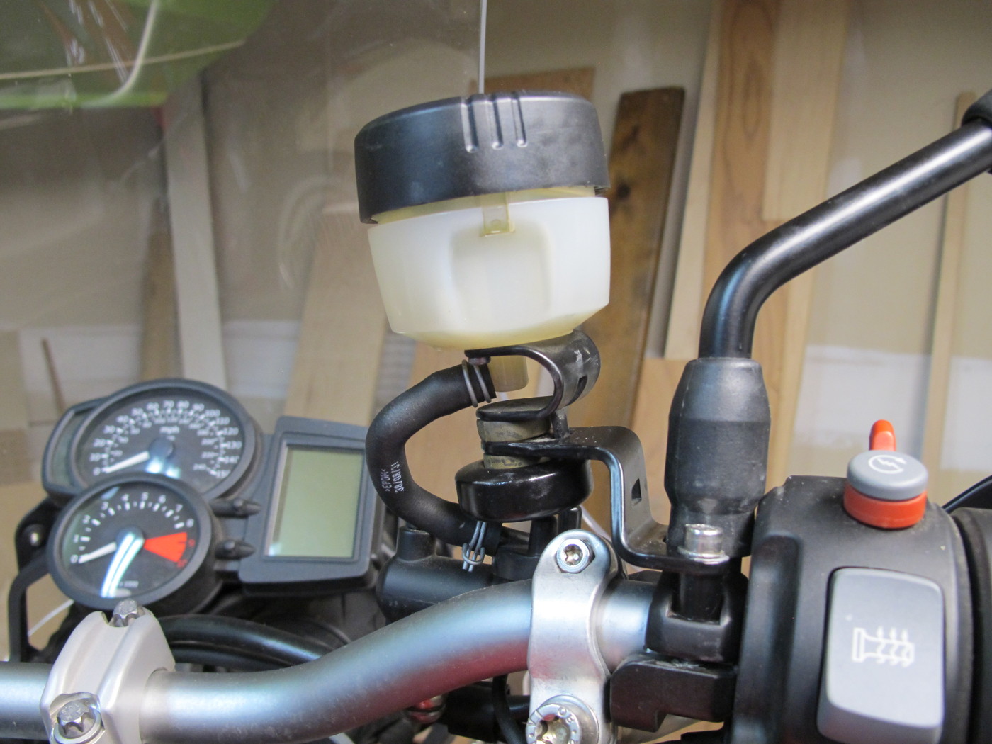
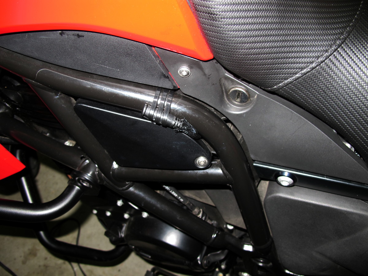
The only part of the job that I’m not happy with is the heated clothing connector.  The very short wire on the clothing left few options.  The following works, but I’m going to see if I can come up with something better than tie-wraps.  It works, as-is, provided I don’t try to stand up on the pegs.  The other end of this connector is the red and black wiring in the first photo.
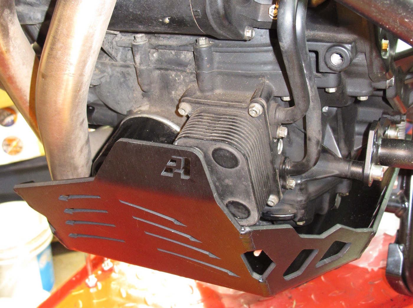


Installed AltRider Skid Plate and Sargent Seat

Mileage: 10,029

Maintenance Summary:

My hopes that the BMW seat wouldn’t be as uncomfortable as others had reported were dashed after only two 80 mile rides.  Sargent had a pretty good Black Friday special going — 15%off and free shipping — so I ordered a new seat.  It arrived today.  Sitting on the seat in the garage it’s not immediately obvious that it will be any more comfortable; in fact it felt a bit cramped.   However, I’m not going to judge it until I’ve put some miles on it.  It appears to be well made.

New Sargent Seat, AltRider Skid Plate and Crash Bars

With both the oil and coolant changed it was finally time to install the skid/bash plate.  The AltRider model was more expensive than those from other manufacturers, but in this case it’s obvious that you get what you pay for.  The skid plate is thick aluminum and very well made; I don’t think it will bend before the rubber mounts shear.  All of the seams are welded, which I like better than the rivets used on other brands.

Installation was easy.  The only trick is to leave the front bracket a little loose before mounting the plate and putting in the front engine bracket bolt.  I did this to get the bracket properly aligned.  I then took the plate off and tightened the bracket bolts before re-installing the plate.

As you can see, the skid plate should do a great job of protecting the oil filter and heat exchanger.   Without any stock protection provided by BMW, not even a plastic guard, the engine fluids seemed excessively exposed to damage on this engine, even when riding on paved roads.

The black color makes the plate almost invisible, in spite of the edgy design.

Changed Coolant

Mileage: 10,029

Maintenance Summary:

  • Changed Coolant
    • BMW Coolant 50/50
    • Put Loctite on both oil cooler coolant tube keeper screws.
  • Cleaned air filter with compressed air.

The coolant is drained at the lower tube on the heat exchanger located on the bottom, front of the engine.  The coolant that came out was very clean.

AltRider Skid Plate

The single screw holding the tube against the block was a bit too easy to loosen.  I reinstalled the screws for both tubes with Loctite.

As you can see in the next picture, the 12 x 17 x 2.5mm o-ring didn’t come out with the tube.  This o-ring is supposed to be replaced with each coolant change, but the local BMW dealer didn’t have one.  I find that odd given how many of these they should be going through when they service these 800cc twins.  The dealer claimed only 10 dealerships in the country had any in stock.  Come on BMW, how much can it possibly cost to require your dealers to stock regular maintenance parts that retail for less than $2?

I’ll order some of these for the next coolant change and replace both o-rings then.  In a pinch — pun intended —  if I damage this one, O’Reilly’s Auto Parts did have one of these in stock.  Unfortunately is was part of a more expensive assortment kit.

The o-ring size is 12×2.5 mm where 12mm is the inside diameter

Here I’ve slipped the o-ring back over the tube for re-installation.   I’ll clean this up a bit more and use a little silicone grease on the o-ring per the service manual when I reinstall the tube.

It’s pretty clear that the specified method for draining the engine leaves a lot of coolant in the system.  The tube in the picture above goes up to the lower radiator hose at the bottom of the water pump.  Due to the location of the thermostat in the radiator, the radiator hose doesn’t attach at the lowest point on the radiator, and the radiator doesn’t have a drain.

Squeezing the lower radiator hose helped drain a bit more fluid from the system, but I suspect there’s still quite a bit of fluid in the bottom of the radiator.  I’m not flushing the system this time, but if I did, I’d flush with new coolant as there’s no way to get all of the flush liquid (e.g. water) out of the system.

Lower heat exchanger tube connects to the lower radiator hose.

It seems that these engines are notoriously hard to bleed, so I bought a vacuum coolant system with the hopes that it would make my life easier.  I was a bit worried about using this FJC 43610 kit because of its height.  I worried needlessly.  It turns out I could get a seal without any difficulties even though I couldn’t insert the cone at the correct angle.  The engine air intake, visible behind the gauge in the picture below, limits the vertical clearance above the radiator cap..  If this hadn’t worked, I would have found and fit a right-angle adapter between the cone and the tool’s manifold block.  In the picture you can also see a small vice grip I used with a bit of burlap to act as a clamp on the hose going to the expansion tank.  Did you notice the collapsed radiator hose?

I was quit surprised that it only took about four seconds to pull a vacuum using the Venturi vacuum generator.  I’m glad; I don’t have a large compressor.

FJC 43610 Vacuum Coolant Filler.  Coolant is hung from the hand guard using a zip tie.

Before inserting the tool into the radiator I put my finger over the end of the cone to form a vacuum and then slowly opened the red valve until the tubing was primed with coolant.

In the picture above I’ve drawn a vacuum, but haven’t started filling the cooling system (both valves are closed).  You can see the tubing which goes up to the coolant supply jug is free of air.

While the FJC seemed to work exactly as expected in terms of pulling a vacuum, holding a vacuum, and drawing coolant into the system, when the vacuum was depleted, I found there were still a lot of air pockets in the system.  I idled the bike for several minutes with the radiator cap removed, watching quite a few  burps and topping off as needed.   I also bled the screw at the water pump several times without the engine running.  I was getting a bit of air at the start.

Coolant Bleed Screw

I think the system is bled now.  I ran the bike for quite a while in the garage, and while the temperature gauge went up to its usual mid-scale reading and stayed there, I could never get the fan to come on, even when reving the engine.  It was cool in the garage.

The vacuum filler system isn’t the cure-all I’d hoped it would be, but I suspect it did make things easier.

While I had the covers off, I pulled the air filter and cleaned it with compressed air.  Except for a couple of bugs, it was pretty clean already.


Changed Brake Fluid

Mileage: 9,930

Summary:

  • Changed Front and Rear Brake Fluid
    • Flushed ABS (using GS-911)
    • Prestone DOT-4 Synthetic
  • Rotated front reservoir rubber bushing

Changing the brake fluid on this bike is relatively easy.    I used the brake-pump method to flush and bleed the brakes.   Normally a two-person job, on this bike it was just possible for me to reach and depress the rear brake pedal while simultaneously reaching around the rear tire to open and close the bleed valve on the opposite side of the bike.   The front is easier to do solo than the rear as the brake lever and single caliper are both on the right side of the bike.

Helpful Hint:  Remove the screw holding the rear brake fluid reservoir to the frame and move the reservoir away from the bike, temporarily routing the hose as shown below.  This is how I was able to get it to hang in free-space making it much easier to fill while also reducing the chances of spilling brake fluid onto the bike’s painted surfaces.  Not shown are the rags that I used to keep any spill that might occur off of the bike.

Detach rear reservoir from frame and position as shown for easier filling while bleeding

Steps used to change the fluid on each brake:

  1. Flush and bleed per BMW instructions  (see note at the end of this post)
  2. Enable the ABS pump using GS-911
    1. Press the brake pedal/lever for two seconds three times while the pump is on (for ten seconds).
  3. Flush and bleed a second time.

This job took less than an hour.  Next time I think I could do it in less than 30 minutes.

Helpful Hint:  You don’t need a special tool to remove the front reservoir cap, though you can buy one if you want.  All you need to do is wrap a piece of string, or thin wire around the reservoir in the gap below the cap.  Pull tight to compress the two locking tabs and then unscrew the black cap.  Worked for me.

Using a piece of string to unlock the front reservoir locking tabs

I’m not sure what BMW engineers were thinking when they came up with this bobble-head design for mounting the front brake reservoir.  Besides being ugly, and distracting while riding, over time the constant pressure applied by the preformed hose causes the reservoir to tilt as rubber grommet looses strength where heavily compressed.

Less tilt after rotating the rubber grommet 180 degrees
A Quick Fix for the Tilting Reservoir

After making sure the reservoir lid was tight, and protecting the bike with rags, I removed the screws holding the bracket at the mirror, and then removed the hex-head bolt holding the reservoir counterweight to the reservoir bracket.  This allowed me to rotate the rubber grommet 180 degrees.  I wasn’t able to rotate the grommet in place as the rubber was stuck to the bracket.  Note: When I say rotate I mean around a vertical axis. I don’t mean flip from top to bottom.  The later would require complete removal of the grommet from the bracket.

Rotating the rubber grommet had the intended effect of making the reservoir sit more upright as shown above.  How long this will last remains to be seen; the hose is still pulling on the reservoir.  The grommet (BMW #62 21 7 670 749) is available for about $3.  I think I’ll add a couple to my next parts order.

The counterweight bolt was reinstalled with blue Loctite.

Note:  If you plan on buying the expensive BMW DVD Service manual to learn about how to work on your ABS brake system, don’t bother.  It’s not covered. The only thing I learned from the manual is that there’s a bleed valve on the front master cylinder.

Added Kaoko Cruise Control

Mileage: 9,811

When buying a throttle lock, or cruise control, I found I had limited choices in terms of what would work with the BMW hand guards.  Fortunately I could still find the Kaoko CCF900 available from a few vendors.

What I couldn’t find were pictures of this specific model, the CCF900,  so I’m making those available here.  As you can see, there are only three parts:  the reverse-threaded center hub with rubber o-ring, the outer nut, and the thrust washer.  It looks well made.

As for the installation, it took more time to take the pictures and edit this blog than it did to install the product.   I did have to pull out a bit on the guard in order to get the steel tubing over the end of the cruise control even though the grip was properly aligned on the bar.  The product seems to work well in the garage, so I expect it will work well on the road as well.

Kaoko CCF900 with BMW hand guard and heated grip

Installed OEM Hand Guards and SAE Accessory Plug

Mileage: 9,811

Today I installed BMW Hand guards.  Why BMW and not Barkbuster or some other after-market brand?   Well, in this case I think the BMW design is the best.  Most of the hand guards are aluminum, which is fine for knocking the brush out of the way.  However, I suspect the aluminum is more likely to bend if the bike goes over.

The BMW hand guards use steel tubes.  They’re strong!  I suspect it would be hard to break a clutch or break lever with the BMW solution.

A second reason I went with the BMW solution is that there’s no advertising on the plastic guards.  Frankly, I don’t want to be a rolling advert for Barkbusters.

The BMW guards come with aluminum bar ends to replace the heavier steel ends that came with the bike.  Given the weight of the steel tubing used in the guards I don’t expect that the handlebars will feel any different.

I fitted the large plastic guards with the optional spoilers to the steel bars.  Mostly I’m seeking a little more wind and rain protection.   The plastic guards need to have two holes drilled in them before the spoilers can be attached.  I don’t know why, but BMW chose to provide shiny bolts to attach the spoiler to the guard.  I think black bolts would look much better.  I may replace those bolts at some point in time.

One problem with the factory guards comes with the availabilities of  throttle locks.  Fortunately I was able to purchase a compatible Kaoko, but it appears that that particular model may have been discontinued, so there’s not a lot of stock available.

The bike was lacking an SAE plug for attaching accessories, or a battery tender.  I installed a fused connector directly onto the batter with the plug end tucked in below the handlebars on the left side.  It has a cover and tucks away out of sight when not in use.

Installed AltRider Crash Bars

Mileage: 9,811

Today I added AltRider Crash Bars.  I purchased them directly from AltRider.

Why AltRider?   Three reasons:

  1. Best mechanical design in terms of crash protection
  2. Best materials (stainless steel — no rusty scratches)
  3. Cleanest design (no visible nuts and bolts)

Most of the other crash bars that are available, including the factory bars, tie into mounting bosses on the front of the engine.  I don’t think this is a good idea.  It might help a little in terms of forces pushing the bars towards the rear of the bike, but a lot of the force in a crash will be from the side.  These front mounted solutions are likely to be much stiffer, which means  a lot of shock force will be transmitted to the front engine bolts as a shearing force.

The Altriders top mount fits into the frame providing a strong anchor against forces which push the bars rearward.  There will be some shearing forces on the bottom engine case bosses, but that’s true for all designs as they all attach at those locations.  Without being rigidly mounted to the front engine bosses, it looks to me like the AltRider bars are better able to transfer stresses to the other side of the bike and are more likely to flex, which if true would absorb some of the shock stresses and reduce the potential for cracked engine cases.  That said, I don’t know how much the bars will flex, they’re pretty stout.

The AltRider bars don’t look bad, but I think some of the other solutions look a bit more integrated with the bike’s styling.  However, for me, it’s function over form when it comes to crash protection.

I chose not to install the upper crash bars at this time.  I don’t know that they’ll add that much more protection. I do know that they’ll add weight higher up on the bike.

Pictures to follow.

New Front Tire, Oil Change, and Chain Maintenance

Mileage: 9,811

Summary:

  • Installed new Michelin Anakee III front tire
  • Changed Oil and Filter (BMW filter, 3 quarts Mobil 1 Racing 4T 10W-40)
  • Cleaned and lubricated chain
  • Checked chain tension:  30mm — no adjustment required

The front tire was well into the wear bars when I bought the bike.  When I went out for my first ride on that tire I discovered that the bike would tend to dive into corners — a problem that went away with the new tire.

The PO had already replaced the rear tire with a Michelin Anakee III.  I don’t know how many miles are on that tire, but it looks new.

There seems to be a lot of conflicting information about these tires.  Some swear by them, others refer to them as Panikee 3’s.  Many say they are loud at freeways speeds, not surprising given that the tread pattern crosses the middle of the tire, while others don’t notice them.   Some call them a 90/10 tire while others refer to them as 70/30.

Having recently changed four tires on two bikes, a job I detest, I got lazy and had the local BMW dealer mount and balance this one.

I took the bike for a short ride to top off the fuel tank, warm the bike up for an oil change, and check the new tire.  The bike handles much better.  I didn’t get above 60 MPH, but at that speed and below I couldn’t say that the tires were noisy.

While the engine was still warm  I changed the oil and installed a new filter.

The chain needed a good cleaning.  Using a toothbrush and kerosene I spent quite a bit of time getting all of the dirt and built-up wax off of the chain.   The chain now looks brand new and doesn’t look to be worn except for two outer and adjacent links that have a bit of corrosion on the outer plates.  I also checked the chain tension, with 30mm of play it was at the tight end of the 30-40mm spec, so no adjustment was necessary.